Beam Cart
Goal
The goal of this project is to transport a 8020-1010 aluminum bar (in vertical position) across a 10 feet-long path in the smallest time possible. To achieve the motion we are given one stepper motor to control with an amplifier and Arduino. The main objective is to create an efficient cart with all the components needed that arrives exactly with 0 velocity at the end of the path.
This project aims to get experience with Closed Loop Control. This is a control system where the output is continuously monitored and adjusted based on the difference between the desired and actual states. In the context of a motor, in this case the TS-25GA370H, closed-loop control involves using feedback (“how much rotation”) to maintain precise control over the motor's speed.
Ideas
Before the actual assignment the professor asked us to come up with some creative ideas for a possible method of transport for the bar, and here are some of mines.
Design
After some ideas we decided to come up with the simplest structure, one that allows us to spend less time on the manufacturing side and focus more on the optimization of the acceleration curve.
Comparison between virtual and real model.
Data Analysis
The next step was to decide what kind of acceleration curve we wanted to achieve. We decided to have a constant acceleration instead of an initial and brutal one (with constant speed after) because in doing so we avoid the first rapid stage that might cause the bar to tip over. At this point we started to use Motion Analysis in SolidWorks, a tool that incorporates the effects of Motion Study elements such as forces, springs, etc. From the simulation we obtained a minimum time of 7.75s with an acceleration of 8 in/s^2. A value a bit overestimated, most likely due to the friction coefficients of the materials and small error of mesh-calculations for physical interactions in the SolidWorks model.
Acceleration curve prediction.
Simulation.
Manufacturing
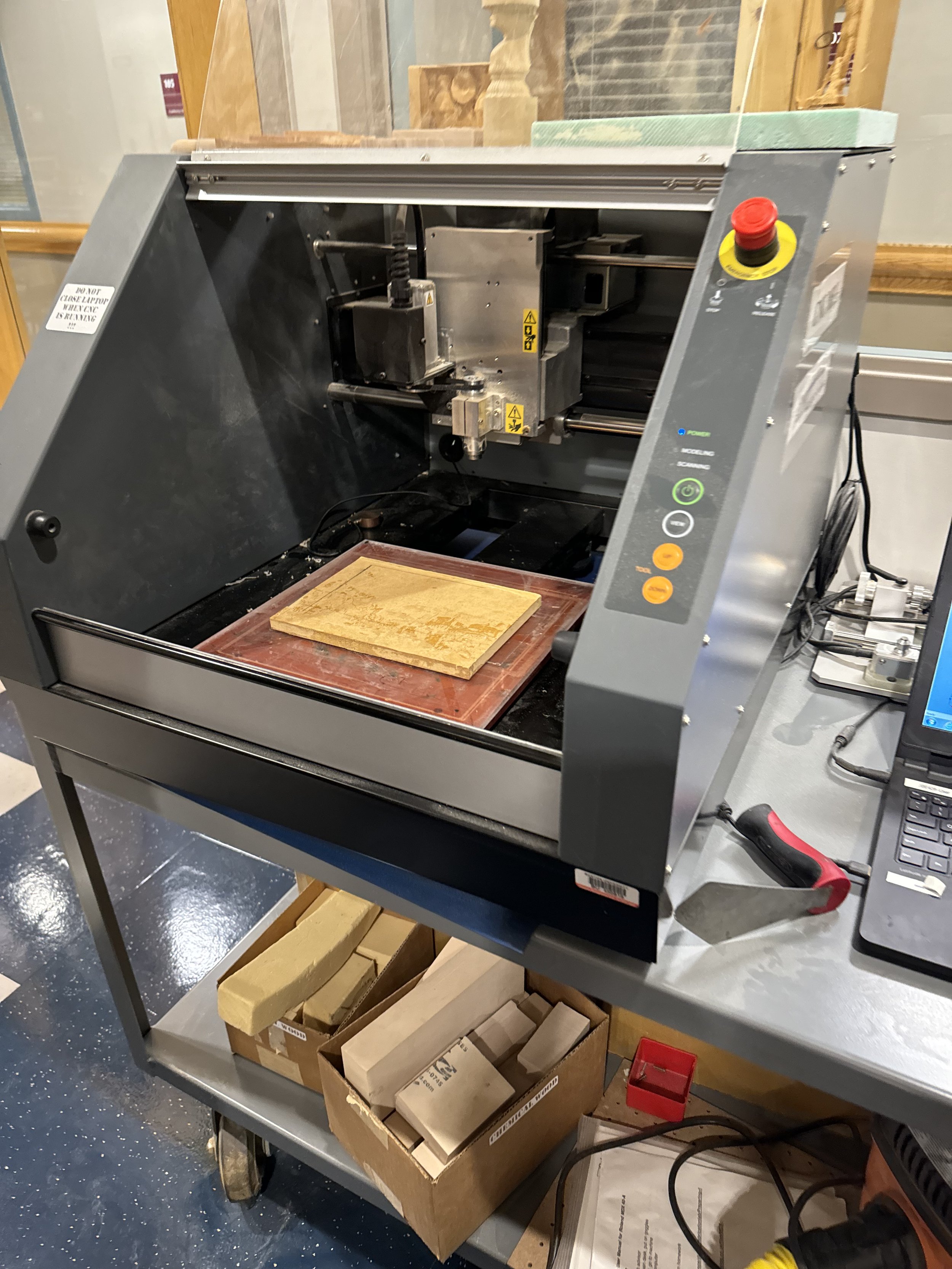
We 3D printed in PLA the parts of the main body, used laser-cut plywood for the back wheels, and normal wood cut with CNC mill. For the top plate we CNC’d a piece of wood to make it fit perfectly the upper plastic frame. With an acceleration of 8 in/s^2 and a wheel diameter of 1.94in, we are getting a maximum speed of 251 RPM. Since this motor has a maximum speed of ~270RPM, we thought additional gears could be avoided.
Upper plate in wood in CNC machine.
Front wheel manufacturing with manual mill.
Results
We ended up substituting the front wheel because it wasn’t smooth, instead we placed a laser-cut plywood wheel. In real life the maximum acceleration we achieved has been ~5 in/s^2, which is way less than the 8 in/s^2 predicted. Also the total travel time ended up being 9.8 s instead of 7.5 s. This is because the simulation does not take into account manufacturing defects, frictions, instability, etc. Overall we can say we are satisfied we the result obtained.
Testing day video.
Final result.


