Smart Bike Light
How does it work?
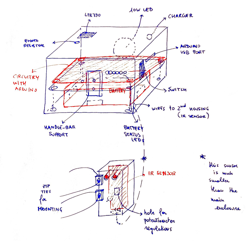
The brightness of the light depends on 3 variables: ambient light, UV light and speed. Each of them has a “weight” of importance (20%, 50%, 30% respectively). The ambient light is a result of 2 sensors working in pair (a light-dependent resistor and the ambient light sensor of the LTR390), in this way it is possible to reduce the variance in the data. The UV light is computed by the LTR390 and the speed is computed thanks to a IR module mounted close to the wheel (we will get into that in the next part).
Speed detection
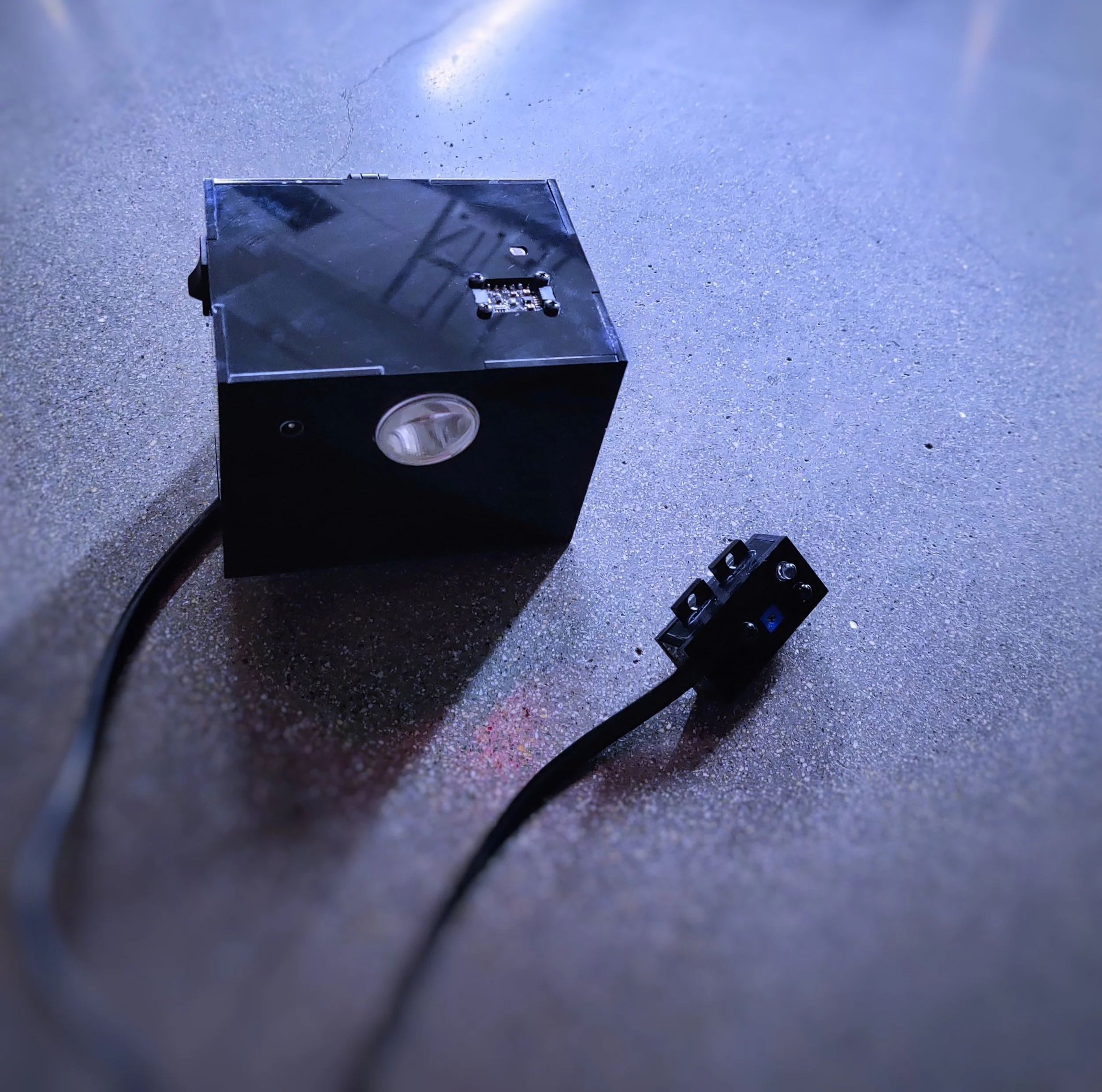
To detect the speed of the bike I opted for an I.R. module mounted close to the wheel (see the little black device in the picture). On the wheel is needed a white sign that will be recognized every time it passes in front of the I.R. module. Since the distance of one wheel revolution (the diameter of the wheel is already known) is calculated as a normal perimeter and the time is calculated by the I.R. module, the speed is easily computed (v=s/t).
Battery Status
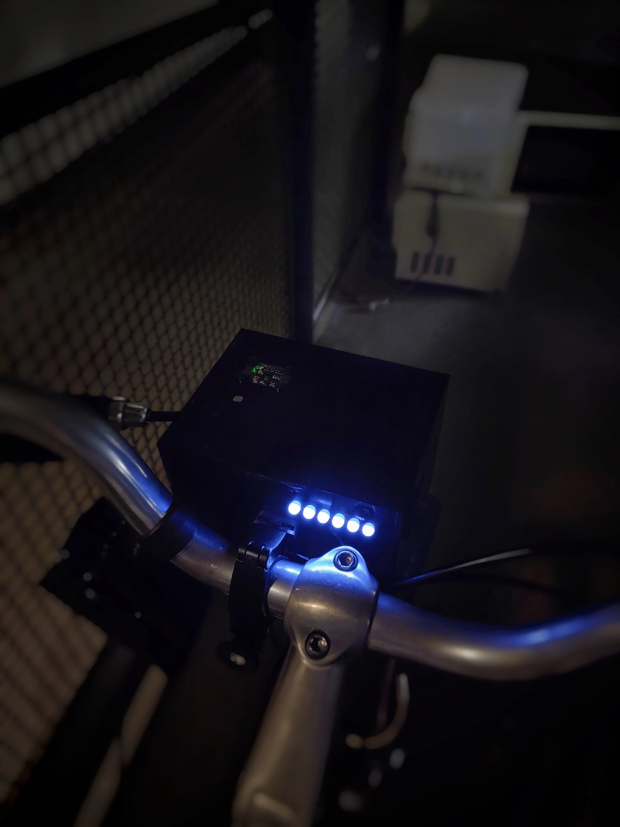
To indicate the battery status I implemented a simple circuit with a voltage divider. The Arduino reads the voltage from a pin and a graph is used to know how charged is this particular type of battery. After this, the right number of LEDs is turned on based on the battery status. In the picture the battery is fully charged.
Enclosure
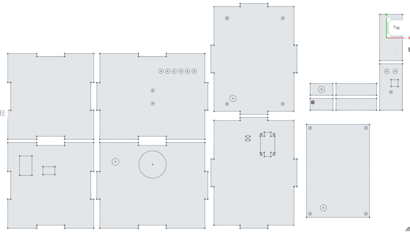
This is the 3D CAD model made on OnShape. This was then used to laser cut a ⅛” black acrylic sheet (screws and super glue were then used to put the pieces together).


